Adding A Second Port To The Pico Packet
Adding a second serial port to the PacComm PicoPacket
I don’t know about you, but I think my PicoPacket is a wonder of
modern engineering…. Sure, I think it is a tiny bit too large, but it
is several times smaller than most other units on the market. The size
reduction is gained from using surface mount parts, and also going away
from the traditional CPU with external Serial IC, to an IC with integrated
Serial Port.
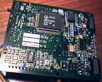
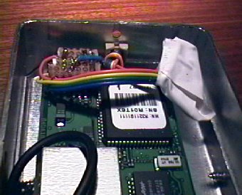
The Z80 CPU found in most TNC’s has been replaced with a Z180 CPU. This
small surface mount IC reduces a lot of the complexity of the TNC.
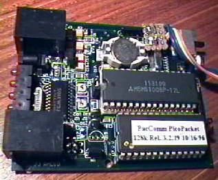
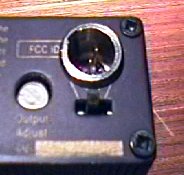
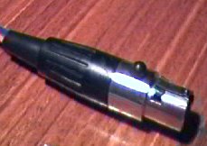
The photos that follow will lead you through the connection of a Motorola
Oncore to the PicoPacket. The Motorola Oncore has uses TTL levels so is
quite easy to interface. It can connect straight throgh to the second serial
port.
WARNING: DO NOT CONNECT RS-232 LEVEL SIGNALS TO THE SERIAL PORT YOU
ARE ABOUT TO ADD.
 |
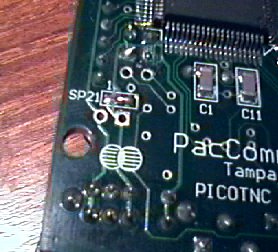 |
| Pin 1 | 5 Volts (or higher depending on SP21) |
| Pin 2 | Received Data – TTL Level |
| Pin 3 | Ground |
| Pin 4 | Transmit Data – TTL Level |
 |
 |
 |
 |
 |
 |
Once you have wired everything together, you can test the setup. The
first test is to monitor the data stream coming from the GPS with a CRO.
If it looks good you are almost assured of success. Now we need to set
up the TNC
Go into the command mode of the TNC and type
GPS
OFF
This will disable GPS from the external serial port and force data from
the new second serial port.
BAUD
Follow the instructions to set the GPS bit rate. This will normally
be 4800 bps.
Once set, pressing CTRL-E or CTRL-D will often bring up the data from
the GPS. If someone wans to write a bit more here, please let me know.
For more information contact me