The Concept
To give
the demonstration some appeal, we needed a gimmick � and the obvious gimmick
was with the object that we were tracking. After looking at a few options
we settled on children�s scooters that have become popular recently.
We decided
to have two people race the scooters outside the venue of our demonstration,
whilst being tracked on a video screen inside. To make the race a little
more exciting, one of the contestants took a somewhat shorter alternate
route.
During
most of the race the only image shown was a live 3D representation. At
the end, closed circuit television was used to show that this was not faked.
Tracking the scooters
GPS
was used to track the scooters. This was not ideal for low speed vehicles
in close proximity but it performed well enough.
In order
to operate flawlessly we had already chosen radio transmitters with a 50W
(max) power output so that we could gain range and cut through any interference
experienced.
This
was important as the original concept called for tracking cars over a larger
area where the power would be needed for the range.
The scooters
we ultimately decided to use for the demonstration were the larger battery
powered units. But with these units we had the problem of where to mount
the radio, GPS and controller. We found that if we removed the internal
battery, making the scooters self powered, we could mount most of the equipment
in the battery compartment.
Equipment
We decided
to use Kenwood D-700 transmitters with integrated TNC�s as they were tightly
integrated making them less likely to fail. The radio was connected to
an AISIN GPS receiver purchased surplus as well as to a custom controller
for triggering transmissions. These three objects were mounted in the now
empty battery compartment.
With
this much equipment in the battery compartment there was no room to mount
a battery with the equipment. We eventually mounted a 7 AH battery on the
back of the scooter with Duct Tape. [If we had been allowed to make major
modifications we could have fit the battery in, but our sponsor wanted
to give the scooters to his children after the demonstration]
The
D700 front panel was mounted on the handle bars, along with the GPS antenna.
A small magnetic mount was also mounted on the handle bar column.
With the
D-700 in POSITION mode, this made the scooters the ultimate toy with the
GPS based speedo function. Several people we showed the scooters to believed
that we should just sell these and make a killing � even more so when they
realized that they would know where their children were at all times.
Technical Implementation
In order
to track the scooters in near real time, we needed to have the D700 transmit
at least every 2 to 3 seconds. Every second would have been better, but
every 2 to 3 seconds was acceptable. Unfortunately the quickest beacon
rate of the D700 is 10 seconds, which is enough for most applications,
but not ours.
The
D700 radio has a GPS port for parsing GPS data in many formats. In TNC
mode, there is a command called LTMON which allows the GPS data tobe
monitored automatically on the serial port. For instance when the command
LTMON 3 is issued, GPS data will be sent to the serial port every three
seconds.
The
GPS data is returned in a string starting $PNTS, a proprietary format designed
by the makers of the chipset in the Kenwood radio. Since our application
was for customized receiving software, any line starting $PNTS was simply
sent over radio using converse mode.
We implemented
this using Rabbit Semiconductor microcontrollers attached to their development
boards. In a production environment we would probably choose a different
processor.
Data Reception
The
receiver was a Kenwood TM-251 radio connected to a Kantronics KPC9612 TNC.
Since we were only receiving at 1200 bps, both these pieces of equipment
could have been downgraded but allowed for reconfiguration if required.
The
TNC was connected to a 150 foot CAT-5 serial cable onto a stage where the
demonstration of this technology was taking place.
In the
field,a D7 handheld with internal
TNC was used to monitor the performance of the scooters so that we could
fix any problems. After operating perfectly for a few days before hand,
we actually needed to reprogram one of the TNC�s just before the demonstration.
Server Software
The
server was responsible for reading GPS data from the rs232 connection,
processing the input stream and separating the two streams of data. The
software also moved the GPS coordinates into the coordinate system used
by the 3D model � by stretching, rotating and scaling the coordinates.
It also acted as a TCP/IP server for clients to connect to.
We extended
this a bit during testing when we found that GPS data was not a perfect
match for a small vehicles on a short race � so we placed a model of the
path into the server as well. This allowed us to use least squares approximation
to find the closest point on the path to the GPS data if required.
It also
allowed us to build extrapolation for the GPS data to remove the jerks
in movement � which is important when video moves as 30-60 frames/second,
and the GPS data was arriving at 3 second intervals.
Having
a server allowed us to run more that one client displaying the graphics.
This was important since we were beta testing hardware for the highest
performance. It also allowed us to tune the incoming data to the format
required by the graphics engine client software. We could also play back
GPS data to the clients in case of system failure.
Client Software
For
each valid data point, the server processes the data and sends to the client.
The
client, programmed in C++, allowed for dynamic control of the viewing location
with the keyboard and mouse. The controls included pan, tilt, zoom etc.just
as if this were a real camera. The client also stored a copy of the 3D
database as well as the Maya 3D real time graphics engine.
This
software required a copy of the 3D model on the local PC to improve processing.
The software that we wrote has the potential to revolutionize the GIS industry.
Computer Modeling
Whilst
it is outside the scope of radio, creating a 3D model of the area is probably
the most important task of this exercise. I am detailing it here to give
an idea of the sheer amount of work involved at the moment.
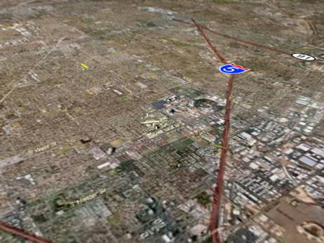
The
first step was to commission some aerial photography, of the whole area
of interest in general, and closer up images of the area of the demonstration.These
photographs were provided as large (200+ Mbyte each) TIFF files. Using
the 3D Studio Max and Maya we were able to create a seamless transition
so that when we zoomed into the area of interest, the higher resolution
image was inset. Figure two shows these files.
Although
this only created a 2D representation of the area, looking onto the map
side on did look 3D until zoomed in close. This is when the magic really
happens.
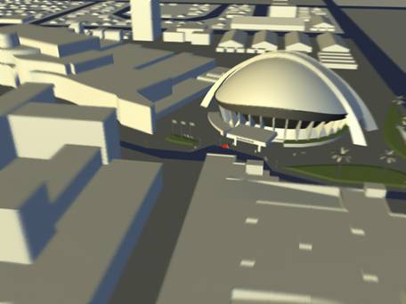
With the
2D representation as a backdrop, the REZN8 artists created a 3D model of
the local area by hand. This involved adding everything from roads to buildings
and letter boxes.
This work
was assisted with lots of photographs taken from ground level as well as
some artistic license. This sort of effort is quite labor intensive, and
not the sort of task to be undertaken lightly.
Discoveries and Challenges
When
we started analyzing the problem of viewing the data we came across the
height information from the scooter � or more correctly found that the
GPS sentence that we were using did not contain height data. Upon analyzing
the problem, we worked out that the height data was not useful to us anyway.
The
height data from GPS contains a higher error than the latitude and longitude.
More importantly, in most cases when visually modeled, the height data
needs to be the most accurate. It is not easy to tell if an object is one
meter too far to the left or the right, but it is very easy to tell if
they it is one meter off the ground, or embedded one meter into the ground.
When
we thought about the problem, there was one obvious solution � we should
always have the moving object at exactly ground level. Since scooters do
not fly despite what you may have seen in�Back
to the Future�, this was perfect.
The GPS
receivers that we were using performed extremely well in most cases. However
they do not like to change hemispheres of the world without a hard reset.
We spent well over an hour on top of a Hollywood
car park before discovering this.