|
Modifying an ex-Galaxy (Conifer) antenna for 802.11

 Welcome to my instructions on modifying the Conifer antennas commonly used
by Galaxy TV for their former MMDS Pay-TV service. This service operated
on 2300-2400 MHz. When they went bankrupt they
left their equipment installed. This has led to a large quantity of it
endin up in the 2nd hand market
Welcome to my instructions on modifying the Conifer antennas commonly used
by Galaxy TV for their former MMDS Pay-TV service. This service operated
on 2300-2400 MHz. When they went bankrupt they
left their equipment installed. This has led to a large quantity of it
endin up in the 2nd hand market
These antennas are not bad - but need a bit of work for them to work
with 802.11 networking. The first issue is that they are
designed for TV. This is not normally a problem since radio waves do not
know the difference. In this case there are a couple of problems - firstly
the dipole antenna is connected to a pre-amp for receive only use, and
secondly the connection to the outside world is 75 Ohms.
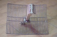
DiPole Separation
When you remove the pre-amp assembly there is not enough mechanical
strength to hold the dipole holder plastic to the antenna. There
is a relatively simple answer.
The answer is to use the existing downconverter assembly, or
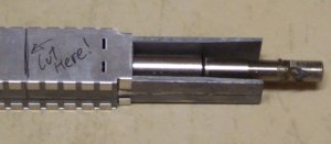 at least the last 100mm of it... Just measure 100mm from the end
of the aluminium assembly furthest away from the dipole. Now using
your angle grinder cut right through everything. YES. Everything. Now
remove the upper and lower shielding.
at least the last 100mm of it... Just measure 100mm from the end
of the aluminium assembly furthest away from the dipole. Now using
your angle grinder cut right through everything. YES. Everything. Now
remove the upper and lower shielding.
Remove the remiaining circuit boards - side cutters can be used with
plyers to unscrew the two bolts. You will need to de-solder one of the
boards from the F-Connector device. Then place the F connector
device and Aluminium in a vice. Now comes the fun part... Programmers
should not attempt this without adult supervision (and adult supervision
is not another programmer)...
Get an electric drill with a 5mm drill bit, and drill down the guts
of the F connector unit... You might need to remove it
from the Aluminium first, but drill right through it. You will smell
some melting nylon or something. That is OK. You will then be left
with a hollow tube. Make sure you can pass your LMR-200 through it. If
not, make the hole bigger.
You can now put the Aluminium and the F connector into the plastic housing
and connect them to the cast aluminium on the end. Then take the nut
that was on the F connector and tighten it. Everything is now mechanically
secure!
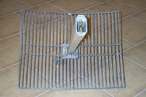
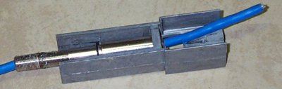 Connect the LMR-200 to the dipole as per directions. Remember,
keep the LMR-200 short. You might want to mount an N socket on the antenna
so that things are really short. If pushed you could use a piece
of RG-58 from the dipole to the back of the antenna - at a maximum
of about 12"-18". This should only be a loss of about 0.4-0.6 dB on an 18
dB antenna. (NOTE: The blue cable in the photo is Cat-5 for illustration
purposes only.) Connect the LMR-200 to the dipole as per directions. Remember,
keep the LMR-200 short. You might want to mount an N socket on the antenna
so that things are really short. If pushed you could use a piece
of RG-58 from the dipole to the back of the antenna - at a maximum
of about 12"-18". This should only be a loss of about 0.4-0.6 dB on an 18
dB antenna. (NOTE: The blue cable in the photo is Cat-5 for illustration
purposes only.)
I just checked the calculations on moving a Galaxy antenna to 802.11.
Galaxy was allocated frequency in 2.3-2.4 GHz for their service. 802.11 is
centered between 2.412 and 2.462 MHz. This creates an error of about 1mm
in the length of a 1/4 wave dipole - nothing really. Not enough to worry
about IMHO... If I was woried I think I would be more interested
in the antenna dipole than the phasing stub.
____
Welcome to our Techical Site. If you are interested in an overview, then visit our
Marketing Site
Copyright © 1994-2005
Radioactive Networks ,
darryl@radio-active.net.au
This page was last updated 2005-08-31 16:58:55
This page was last compiled 2005-11-15 19:03:20
Question or Comment? Click
here
|