|
Adding a second serial port to the PacComm PicoPacket
I don't know about you, but I think my PicoPacket is a wonder of
modern engineering.... Sure, I think it is a tiny bit too large, but it
is several times smaller than most other units on the market. The size
reduction is gained from using surface mount parts, and also going away
from the traditional CPU with external Serial IC, to an IC with integrated
Serial Port.
The Z80 CPU found in most TNC's has been replaced with a Z180 CPU. This
small surface mount IC reduces a lot of the complexity of the TNC.
The photos that follow will lead you through the connection of a Motorola
Oncore to the PicoPacket. The Motorola Oncore has uses TTL levels so is
quite easy to interface. It can connect straight throgh to the second serial
port.
WARNING: DO NOT CONNECT RS-232 LEVEL SIGNALS TO THE SERIAL PORT YOU
ARE ABOUT TO ADD.
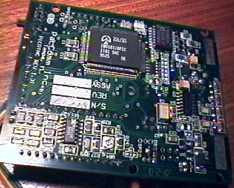 |
This is the underside of the PicoPacket. The upper
right corner is the location of SP21 and the second serial port connection.
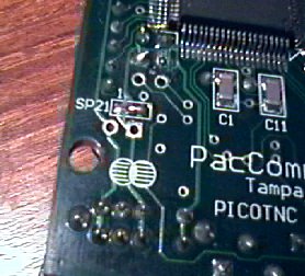 |
PicoPacket PCB showing the location of SP21. Note
that the bridge between pins 1 & 2 have been cut, and pins 2 &
3 have been joined by solder. Directly above SP21 is J1 where connections
to the second serial port are made.
J1 Pinouts
| Pin 1 |
5 Volts (or higher depending on SP21) |
| Pin 2 |
Received Data - TTL Level |
| Pin 3 |
Ground |
| Pin 4 |
Transmit Data - TTL Level |
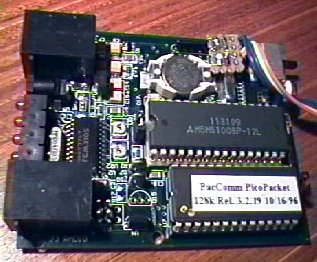 |
This is the top of my PicoPacket showing how I mounted
the header and wired it to the ribon cable. I is not pretty but it works.
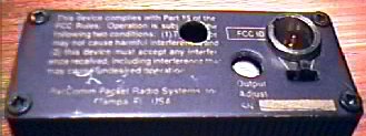 |
This is the back of my PicoPacket. Ignore the hole
in the middle of the FCC statement. That was a mistake. The MiniCannon
socket is mounted just above the ON/OFF switch. It is held in location
by being a tight fit, and also a cable tie at the back.
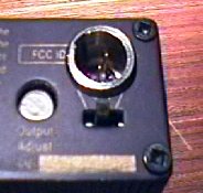 |
A closer view of the socket and switch
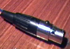 |
This is a picture of the 4 pin micro-cannon plug,
similar to, but much smaller than the ones used on microphones in professional
recording.
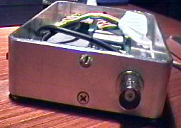 |
This is a view of the Motorola Oncore GPS in the
Horwood Aluminiumn case. The BNC socket on the front is for the GPS antenna.
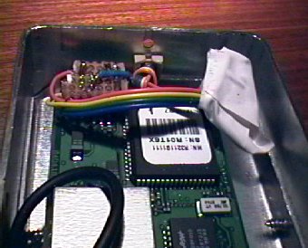 |
Looking at more detail towards the back of the case.
I used a 3.5mm socket as a ferule. Ignore the white electrical tape. I
made a mistake when I was wiring up and needed to make a minor modification.
The ribbon cable is terminated on a piece of matrix board with a row of
headers attached. The GPS was screwed to the bottom of the case.
Once you have wired everything together, you can test the setup. The
first test is to monitor the data stream coming from the GPS with a CRO.
If it looks good you are almost assured of success. Now we need to set
up the TNC
Go into the command mode of the TNC and type
GPS
OFF
This will disable GPS from the external serial port and force data from
the new second serial port.
BAUD
Follow the instructions to set the GPS bit rate. This will normally
be 4800 bps.
Once set, pressing CTRL-E or CTRL-D will often bring up the data from
the GPS. If someone wans to write a bit more here, please let me know.
For more information contact me
____
Welcome to our Techical Site. If you are interested in an overview, then visit our
Marketing Site
Copyright © 1994-2005
Radioactive Networks ,
darryl@radio-active.net.au
This page was last updated 2005-08-31 19:48:39
This page was last compiled 2005-11-15 18:49:27
Question or Comment? Click
here
|