Switching Power Supplies By Darryl Smith, VK2TDS

By Darryl Smith, VK2TDS
These are notes of an impromptu lecture
given to the Fisher�s Ghost Amateur Radio Club on 18 March 1997. They are not
meant to be an introduction into switching power supplies only. One note of
warning. Switching or switch-mode power supplies often operate with high
voltage DC, with large capacitors. These capacitors may take weeks to discharge
if their discharge resistor has blown, and will kill you easily.
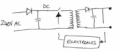
The Diode and the capacitor rectify the
incoming mains voltage generating high voltage direct current. This is done
without using a transformer, so a device is added to reduce the turn on current
to the capacitor.
Once DC has been generated the transformer
is powered by rapidly turning on and off the DC supply to the transformer. The
effect of this is to create a very high frequency AC signal from the DC signal
in a similar way to an audio amplifier.
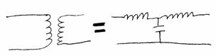
But by turning the switch on and off very
fast the transformer does not need to be as large. Think of a transformer as a
couple of inductors as shown in this circuit diagram. As the frequency
increases more signal can get through the inductors. In effect if you ignore
the voltage change a transformer is not much more than a high pass filter. And
once the inductive losses are reduced as frequency increases, the transformer
can get smaller.
The capacitor and the diode at the end act
like a normal power supply. However as the capacitor is being charged more
often, a smaller capacitor may be used.
Voltage regulation is performed by changing
the duty cycle of the switch, such that the voltage goes up or down. By turning
on the switch longer we have a higher voltage at the output.
Turning a switch on and off fast creates
harmonics which cause problems to other equipment nearby. To remove this
interference, inductors are added on the input and the output.
Since Switching power supplies have no
normal voltage regulator they become up to 90% efficient. Normal linear power
supplies are about 60% efficient. That means 40% of the power going into your
power supply is being lost as heat.
In summary Switching power supplies are
cheaper because
| Transformers are smaller containing less copper
They have no series voltage regulators as in
normal power supplies (Such as a 3 pin voltage regulator)
Output capacitors are much smaller
They are more efficient
They are physically smaller |
Of course these power supplies are more
complex, but with mass production they become much cheaper.
____
Welcome to our Techical Site. If you are interested in an overview, then visit our
Marketing Site
Copyright © 1994-2005
Radioactive Networks ,
darryl@radio-active.net.au
This page was last updated 2005-09-01 09:13:41
This page was last compiled 2005-11-15 19:13:14
Question or Comment? Click
here
|