|
26-May-2002

You would not believe some of the things that I have seen in the 'Wireless Community
Networks' out and about. People who you assume to be at least slightly
professional, but cannot even afford a basic crimp tool for an 'N' type
connector. The Tool is worth all of US$20, so they use a vice. That is not
the way to get things to work correctly.
From my logs I am seeing a lot of people are interested in PRINGLES
antennas. I am still attempting to work out the maths for them. I am sure
that they are not the best antenna to build for the price, and I just need
to do the maths on them. I just need to remember all my microwave
enginnering from uni.
There was an interesting discussion a few months back on the NOCAT.NET
mailing list on the maximum range of 802.11, subject to power being
available. That was never resolved, but the standard does sound as if it can
be stretched in a whole lot of ways that the designers never intended, so
long as you dont mind loosing throughput.
Now for a piece of advice if you are testing 802.11 equipment over long
distances. It works better if you use infrastructure mode rather than
ad-hoc. It will be easier to get a lock meaning that your allignment is much
easier.
4-February-2002
Frequency Source - How? Amplifier and feedback loop. Is Minicircuits better
to build an oscillator.
31-January-2002
Question: How do you test 802.11 Antennas at 2.4 GHz without
test equipment?
Answer: 2.4 GHz frequency source feeding the antenna under test. Use
an old Galaxy TV Antenna and Receiver to test the antenna
at a distance. The fun part is to work out where 2.4 GHz is tuned.
The signal source should be easy and cheap to build - less than $10.
29-January-2002
Started work on the Simple Radio Routing Protocol (SRRP) which is a
protocol designed for wireless networks found in 802.11, where large
bandwidth is available, the links are bi-directional, and there is
little formal structure in numbering or anything else.
The work is based on some of the ideas of RSPF, extended with some ideas
of my own. At the moment it is all on paper, with some of the ideas simply
transposed to WORD in case I loose the writing pad. The protocol is based
on a tree spanning algorithm, with each node knowing only being told about
nodes it cannot hear by the nodes that it can.
I am beginning to see that there can be stability issues, and also the
possability (or probability) of routing loops. I am sure that there is
some way to ensure that this does not happen often, but the protocol needs
some thinking about. My idea is that every wireless node knows about its
neighbours. Therefore every neighbour knows about its neighbours,
etc. Based on this fact it should be possible to build a picture
of the network.
It should also be possible to build a method of update so that the changes
are propagated from node to node, with minor problem if one of the updates
goes missing, provided that the missing update does not cause a circular
route. This may be as simple as internode handshaking before
creating a possible circular route. This might be an 'Understand
before route update', change outgoing routes before informing other nodes
to route through it.
Some type of PING and quick kill is also needed to switch over
to alternate links if a link goes down. Since we are talking
an application level protocol something like ping is needed.
Check out my BOOKS page
with links to AMAZON.COM.
Purchases through this link will help pay for my research into
wireless networking (Or more correctly will provide books for my research).
27-January-2002
Started writing a paper for the DCC on 802.11 and Ham Radio... Why it is
important for us to embrace it, and where ham radio can use 802.11. Much
more work needed. Also started looking at RSPF for 802.11. Put RSPF
standard up on WWW site.
27-January-2002
I have been working on getting my Galaxy (Conifer) antenna up and
running, or more correctly documented. There are now some photos on the
appropriate WWW site page for the GALAXY antenna.
25-January-2002
Downloaded a copy of the Telecommunications Act from
here . It is interesting reading for those building a
wireless community network. I am still working out what the implications
are. I have a feeling that the only way to get arround this is
to get a designation from the Minister for Communications that this we
do not need a carrier licenses.
I have been thinking about the wireless routing issue. There was a comment
on Sydney Wireless about routing
in
mesh. Something
to look at...
I am thinking that RSPF is the way to
go - but it needs some work.
24-January-2002
I just tried the hack described below for mounting the
Galaxy dipole... Seems as if it should work. Cutting
with the Angle Grinder was quick. The only thing was that it was a bit
smelly. Not something to be done in the house (Is angle grinding ever?)...
Then I removed the PCB's... Nice and quick.
The threaded tube was easy too... I used a 6mm drill bit to remove the
core... The procedure was something like drill in, arround, and then
out... And repeat... Eventually the drill bit was too short,
so I started pushing the centre dielectric from the other end and kept
drilling... This lead to a hollow tube. Worked well.. Now all I need is
some LMR-200
23-January-2002
Found a better list of 2.4 GHz losses for coax today so I updated my page
with losses and cable sizes. What surprised me was how good RG-58 was,
compared to RG174 and LMR-100A.
Got offered some
Cushcraft 2.4-2.5 GHz Yagi's... Rather nice too. I will have to make an
offer if I can work out how much they are worth. I think they are ex-Olympics.
Galaxy Antenna... The downconverter board in the Galaxy unit was designed so
that it provided mechanical stability to the plastic work holding the dipole.
Without the downconverter there is little mechanical stability. The solution\?
I am still working on that. I know that the downconverter thread is no good as
it is terminated in an F connector, known for being cheap, and also being
75 ohms.
I personally like the idea of using RG-213 coax from the dipole, and using
some type of tube. Still working on this one. Another idea I am having us
using something like LMR-200.
GOT IT The answer is to use the existing downconverter assembly, or at
least the last 100mm of it... Just measure 100mm from the end of the aluminium
assembly furthest away from the dipole. Now using your angle grinder cut
right through everything. YES. Everything. Now remove the upper and lower
shielding.
Remove the remiaining circuit boards - side cutters can be used with plyers
to unscrew the two bolts. You will need to de-solder one of the boards from
the F-Connector device. Then place the F connector device and Aluminium in
a vice. Now comes the fun part... Programmers should not attempt this without
adult supervision (and adult supervision is not another programmer)...
Get an electric drill with a 5mm drill bit, and drill down the guts of the F
connector unit... You might need to remove it from the Aluminium first, but
drill right through it. You will smell some melting nylon or something. That is
OK. You will then be left with a hollow tube. Make sure you can pass your LMR-200
through it. If not, make the hole bigger.
You can now put the Aluminium and the F connector into the plastic housing and
connect them to the cast aluminium on the end. Then take the nut that was on the
F connector and tighten it. Everything is now mechanically secure!
Connect the LMR-200 to the dipole as per directions. Remember, keep the LMR-200
short. You might want to mount an N socket on the antenna so that things are
really short...
Tomorrow I will actually try this... :-)...
22-January-2002
I just checked the calculations on moving a Galaxy antenna to 802.11.
Galaxy was allocated frequency in 2.3-2.4 GHz for their service. 802.11 is
centered between 2.412 and 2.462 MHz. This creates an error of about 1mm
in the length of a 1/4 wave dipole - nothing really. Not enough to worry
about IMHO... If I was woried I think I would be more interested
in the antenna dipole than the phasing stub.
I still love the idea of putting a USB wireless adapter in the focus of the
antenna...
Seems that Andrew Communications purchased Conifer (makers of the Australis / Galaxy
Antennas) back in 1999. I have been unable to find any information
on the Conifer T5120
antenna. Found
this
while looking... Seems to be the only specs I could find. There is
also a
75-50
ohm converter on the site.
20-January-2002
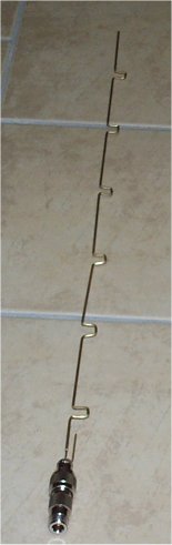
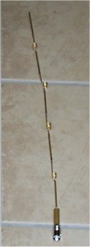
Richard Talbot came to visit today to play antennas. The two antennas we
built are shown here, but neither worked very well... In fact the antennas
worked worse than if we had no antenna at all... It was that bad.
 From Richard
Well, me and a mate [hey, that'e me... ] sat down on the weekend
to build some omni's. We used the Collinear design posted
on the Melbwireless site
here.
Building was reasonably straight forward once we worked out the more
than cryptic documentation and sorted through all the measurements.
A few points of note...
| A 6mm screw with 16 threads per inch didn't exist at our hardware shop.
Even if it had, the pitch would be wrong. There is just
no way one could coil a 3/64 brass rod
around the scree without the coils touching.
The design looks seriously strange to us. There is nothing like it in the
usual sources, ARRL experimenters guide and the like. With no maths
provided it is almost impossible to verify the theory.
We cut all the parts accurately and measured with verniers.
(NOTE: We used a Stanley Knife to cut the parts... Quite easy really) |
 With soldering complete and attached to a SMA connector, we set about to
test it. Initial testing was done with a Compaq WL100 and pigtail. We
were talking to a WAP11 upstairs. We couldn't see any appreciable results
so we figured it would be easier to test if we walked up the street till
we nearly ran out of signal and plugged it in. Once in position 50m up the
street we plugged it in and to our horror saw the SN ratio go down
(- ive scale) about 15db. The card then alternated up and down every
second or so on diversity. The internal antenna presumably doing better
than our "5db" omni.
With soldering complete and attached to a SMA connector, we set about to
test it. Initial testing was done with a Compaq WL100 and pigtail. We
were talking to a WAP11 upstairs. We couldn't see any appreciable results
so we figured it would be easier to test if we walked up the street till
we nearly ran out of signal and plugged it in. Once in position 50m up the
street we plugged it in and to our horror saw the SN ratio go down
(- ive scale) about 15db. The card then alternated up and down every
second or so on diversity. The internal antenna presumably doing better
than our "5db" omni.
We rechecked all our measurements, construction and integrity of the wiring.
Still no go! Just to make sure we weren't dreaming we plugged in one
of the Galaxy antennas I have previously modified from the same place.
After moving the antenna around a bit we notice a 14-15 db gain
on the internal antenna. Considering we had 5m of RG 213 on the end, one
of those terrible Lucent connectors and the Galaxy antenna isn't
really designed for ISM frequencies, we thought this was pretty good. The
score thus far Galaxy 1, homebrew omni's 0.
We then set to building another design. This time a 26 element omni. The
maths we could understand and the design involved simply bending the
brass... so this time we thought we might be more successful. We didn't
actually use the full 26 elements, more like 7. We felt
this antenna couldn't be any worse than the last in any case. Anyway,
back we walked to our original testing place and no joy on
this attempt either although we didn't drop quite so many db's. The score
now Galaxy 2, homebrew omni's 0.
Having got this far we were a bit discouraged, but we decided to press
on and build a Pringles antenna. This looks promising, although
we haven't finished it yet. The design is a well known ARRL one, used
by hams for quite some time. I'll keep you posted.
I'd also be interested in hearing from anyone that has managed
to successfully build an omni with a verifiable gain....
Cheers
Richard.
____
Welcome to our Techical Site. If you are interested in an overview, then visit our
Marketing Site
Copyright © 1994-2005
Radioactive Networks ,
darryl@radio-active.net.au
This page was last updated 2005-08-31 16:47:36
This page was last compiled 2005-11-15 19:04:42
Question or Comment? Click
here
|